The light sensors circuit is electronic circuitthat functions to sense changes in light intensity into electrical signals. Level sensorsensitivity can be obtained from setting the value of signal amplification in the circuit. The series of light sensors can result in twopossibilities, that is active during the dark and active during the light.
Typically the sensor component used in the circuit of light sensor is a Light DependentResistor (LDR). LDR has a resistance that canvary according to level of intensity of light falling on it.
Light sensors circuits are often used to control garden lighting. Park lights will typically turn on automatically when night falls and turns off automatically during daylight.Here are some examples of simple light sensor circuits:
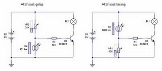 Light sensor circuit
 Light sensor circuit 1
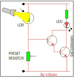 Light sensor circuit 2
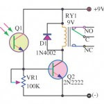 Light sensor circuit 3
 Light sensor circuit 4
 Simple light sensor circuit
 LDR
LDR
Typically the sensor component used in the circuit of light sensor is a Light DependentResistor (LDR). LDR has a resistance that canvary according to level of intensity of light falling on it.
Light sensors circuits are often used to control garden lighting. Park lights will typically turn on automatically when night falls and turns off automatically during daylight.
 Light sensor circuit
  Light sensor circuit 1
 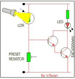 Light sensor circuit 2
 Light sensor circuit 3
 Light sensor circuit 4
  Simple light sensor circuit
 LDR
LDR Examples of light sensors circuit on top of actually having the same working principle. Changes inthe intensity of light received by the LDR will alter the magnitude of the voltage that falls on ldr,which in turn would trigger a transistor voltage at the load circuit.
Komentar
Posting Komentar